Chapter 6 - Just Charge It

Go Home
Go To Introduction
This is Book 1
Chapter 1 - Electricity
Chapter 1.2 - The Numbers
Chapter 2 - Sharing and Bonding
Chapter 3 - Voltage
Chapter 3.2 - Voltage Static
Chapter 3.3 - Batteries
Chapter 3.4 - Solar - Others
Chapter 4 - Resistance
Chapter 4.2 - Parallel Resistance
Chapter 4.3 - Voltage Dividers
Chapter 5 - Semiconductor
Chapter 5.2 - PNP NPN Junctions
Chapter 6 - Capacitor
Back To The Guide
To Book 2
Capacitor and Capacitance
Capacitor in a DC circuit
A capacitor stores its energy on its plates. There is no direct
electrical connection between the plates, so current does not flow
through a capacitor in the traditional concept of flowing. In the
illustration there is a positively and a negatively charged plate,
separated by a dielectric spacer. The plates have the ability to
store a charge similar to a battery but the capacitor can not
generate a change by itself. It is basically a Charge Storage
Tank. It has a zero-sum charge which means that if it builds a
positive charge (8 units) on one plate, it needs to maintain the
exact opposite negative charge (8 units) on its other plate.
The Charge Cycle:
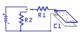
Here is how a capacitor works. Starting with the circuit
illustrated here, we have a 9 volt battery, two resistors, a
switch and a discharged capacitor.
When the switch is flipped up, current starts to flows. Negative
charges from the battery start building on the C1 lower plate and the
same number of electrons flow off the C1 upper plate through R1 and
into the positive battery terminal.
At first there exists a larger voltage drop across R1 thus more
current flowing because C1 was sitting at 0 volts in charge.
C1 starts smoothly building a charge and the R1 voltage drops
smoothly, until at some point in time C1 will be charged to 1 V,
then 2 V's and so on until it is fully charged to 9 volts.
As C1 charges and its voltage ramps up, there becomes less of a
differential voltage across R1. Ohms Law tells us that with less
voltage drop across R1, less current is flowing through R1 thus the
charge rate of C1 steadily slows down. At some point in time C1 is
fully charged to 9V and no more current flows across R1.
At any time in this cycle, when the switch is placed in its center
position, the circuit is opened and, C1 will remain at that charge
level for a very long time.
The Discharge Cycle:
When the switch is flipped to the lower position, and if the
capacitor was full charged, current flows in the reverse direction,
out of the lower plate of C1, through the R2 - R1 series circuit until
C1 is fully discharges. Here again, faster while C1 has 9 V's and steadily
declining current flow until C1 is fully discharged.
Capacitors are made with a specific capacitance and this is measured in
Farads, in honor of the English chemist and physicist Michael Faraday.
A farad is a large value, so often the term microfarad is used to
represent one-millionth of a fared. This term is generally written using
the letter U or as uF, or with the Greek letter as µF. Other common
values are terms including nanofarads written nF, and picofarads written pF.
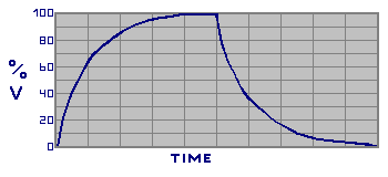
RC Time Constant:
The rate of this charge and discharge is known as the RC Time Constant.
Because more current flows at the start and less flows as time goes on,
the level of the voltage applied to the capacitor charging rate is not
linear. It is considered to take 5-time constants to fully charge, or
discharge a capacitor. At time constant 1, about 63% of the capacitor
charge is filled, leaving 37% remainder charge to go. At time constant 2,
about 63% of that remainder amount is charged, thus placing a total charge
at about 86.5% leaving about 13.5% remaining to charge. And so on, until the
capacitor is fully charged.
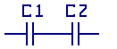
Capacitors In Series
When capacitors are in wired series in a circuit, the current will flow,
charging the capacitors in accordance to the capacity values of the
capacitors. The smaller valued capacitor in the series will have the most
impact over the total charge. This is because its storage capacity is less,
causing the larger component to not be able to be fully charges. Look at
the formulas to see this relationship.
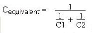
Here is the formula for calculating the total for capacitors in series.
C-equivalent= 1 / ((1/C1) + (1/C2) + (1/Cn))
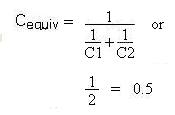
Given: two series capacitors with values of 1F each
C-equivalent= 1 / ((1/1F)+(1/1F)) = 0.5F
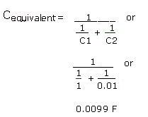
Given: two series capacitors values of 1F and 0.01 F
C-equivalent= 1 / ((1/1)+(1/0.01)) = 0.0099F
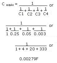
Given: 4 series capacitors values of 1F, 0.25F. 0.05F, and 0.003F
C-equiv = 1 / ((1/1)+(1/0.25)+(1/0.05)+(1/0.003))
C-equiv = 1 / ( 1 + 4 + 20 + 333)
C-equiv = 1 / 358
C-equivalent= 0.00279F
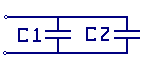
Capacitors In Parallel:
When capacitors are placed in parallel in a circuit the equivalent capacitance
is the sum of the parallel capacitors added together.
Here is the formula for calculating total for capacitors in parallel.
C-equivalent= C1 + C2
Given: two parallel two capacitors, each 1F
C-equivalent= 1F + 1F = 2F
Given: three parallel capacitors, values of 1F, 0.25F and 0.01F
C-equivalent= 1µF + 0.25µF + 0.01µF = 1.26µF
RC Time Constant (TC)
The ONE time constant is the time it takes to charge the given capacitor to the 66%,
level with the given resistor.
Both the resistor (R) and the capacitor (C) impact the charge rate time constant (TC).
1) Increasing the resistor value, reduces the current flow, and extends the charge time.
2) Increasing the capacitor increases the capacity (area to fill) and extends the charge time.
3) Doubling the resistance value while reducing the capacitor value by half will have no effect on the charge time.
4) the formula is: T = R x C
where T is the Time and is in seconds, R is the Resistance in Ohms, C is the Capacity in Farads
5) There are 5 TC to charge or discharge a capacitor
Question 1:
Find one TC with Given: 1 M resistor and a 1 µF capacitor?
Answer: 1,000,000 x (1/1,000,000) or 1 second
Question 2:
Find one TC with Given: 270 k resistor a 0.1 µF capacitor?
TC = 270000 x 0.0000001 gives 0.027 seconds
Capacitive Reactance (XC)
The Capacitive Reactance is equivalent to the AC resistance of the capacitor.
For now, consider the higher the frequency the less the resistance to the change.
This is because we just learned that it takes time for the capacitor to store and to release energy.
In AC circuits, capacitors act a bit different then do most other components.
When the circuit voltage is raising above capacitor voltage the capacitor
tends to take on and store the higher voltage.
When the circuit voltage is lower then the stored charge in the capacitor the
capacitor starts dumps its charge back into the circuit.
The capacitor has limited space on its plate to store electrons
so once the plate area is charged to the circuit voltage the capacitor can not
add to its storage so the effectively the current will stop flowing in the capacitor.
Capacitive Reactance formula is XC = 1/ (2 Π f C)
[1 divided by the sum of (2 Π f C)]
Where - XC is the AC resistance to current flow
2 Π is a constant of 2(3.14159)
f is the frequency of the voltage in Hz
C is the capacitance in Farads
Here are a few examples.
Given: C is 100uf at 1kHz.
Answer: XC = 1/((2)(3.14159)(1000)(0.0001)) or 15.9 Ohms
Given: The same C, 100uf with a higher frequency of 10M Hz.
Answer: XC = 1/((2)(3.14159)(10000000)(0.0001)) or 0.000159 Ohms
Given: C is 0.1f at 10Hz
Answer: XC = 1/((2)(3.14159)(10)(0.1)) or 1 / 6.28318 or 0.159 Ohms
Congratulations! You have just finished our first online book on the topic
of electronics. This material is provided free to support your learning.
This book has an accompanying lab series that
can be purchased directly from Shoebox Kits. Each kit expands on the free
materials provided on this site.
« Previous Chapter Back To The Guide »;
Email us: info@shoeboxkits.com