hapter 4.1 - Resistance and Ohms Law

Go Home
Go To Introduction
This is Book 1
Chapter 1 - Electricity
Chapter 1.2 - The Numbers
Chapter 2 - Sharing and Bonding
Chapter 3 - Voltage
Chapter 3.2 - Voltage Static
Chapter 3.3 - Batteries
Chapter 3.4 - Solar - Others
Chapter 4 - Resistance
Chapter 4.2 - Parallel Resistance
Chapter 4.3 - Voltage Dividers
Chapter 5 - Semiconductor
Chapter 5.2 - PNP NPN Junctions
Chapter 6 - Capacitor
Back To The Guide
To Book 2
Resistance is good
In this chapter we will start bringing together several electrical terms.
To do this we will start by learning about resistors and their electrical
property called resistance. We will study resistors in series, resistors
in parallel and combination resistor circuits.
We will also start talking about something called Ohm's Law and how
voltage, current, and resistance all work together. We will also build
a small circuit.
SERIES:
The term series means that a group of two or more items are lined up
one after the other. Train cars are in series as they roll down the track,
one car after the other.
PARALLEL:
The term parallel means a group of two or more items, and they are lined
up next to each other. In a set of train track rails, one rail is parallel
to the other rail.
New Schematic drawing objects:
In this section these are the new schematic drawing objects for you to learn.
Resistor: The resistor is any device that holds back or restricts the flow
of current. I use the wavy line symbol whereas some authors use the
rectangle box symbol either or both can be uses. My representation helps
those new to the field visualize the characteristic of the component.
Potentiometer: This three terminal resistor has a sliding contact inside.
By turning the knob on a rotary potentiometer or sliding the tab on a
linear potentiometer the user can select any resistance setting from the
minimum the maximum range of the device.
Amp Meter: The amp meter measures the current flowing through the circuit
at the point where the meter in placed INTO that circuit.
Volt Meter: The volt meter measures the voltage difference across an area
or between two points. By setting the volt meter at the proper range and
touching each of the meters two test probes at different locations within
a circuit, the meter will display the difference in voltage between these
two test points.
Test Point: The test point is the place in the circuit to take a
measurement. If only a single point is specified, generally that is the
location for the positive test probe (the red one) and the second test
probe (the black one) will be touched to the circuit common or circuit
ground point.
May I Introduce Ohm's Law
Ohm's law is the first essential equation in electric circuit analysis.
It states that the amount of electric current flowing through a circuit
is directly proportional to the voltage applied to the circuit, and it
is inversely proportional to the resistance. Voltage is measured with
a Volt Meter. Recall that voltage pushes electrons and is measured in
voltage, volts, V, E or EMF. Also recall that current is the amount of
the electrons being pushed through the circuit and is measured in
amperes, amps, A, or I. An "Ammeter" is used to measure current flowing
through a circuit.
The third component to this trio is Resistance. In general terms, a
resistor is any item that tries to hold back or restrict the flow of
current. In electronics, resistors, as components, are manufactured in
specific amounts (values). Resistors are measured in units called Ohms
and labeled with the letter R, the word Ohms, or the Greek letter omega.
There are cases where resistors use other markings and this will be
highlighted when we get to these events. The resistance of a resistor
can be measured using an "ohmmeter".
Ohms Law uses basic algebra. I will step through the math. The Ohms Law
Pie Chart is shown in the next few sections. I like pie. Pie is good.
We will work through one section as a time, and will work through the
whole pie chart
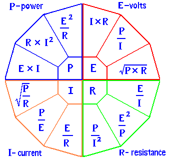
Using Ohms Law
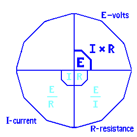
In this graphic there are 3 variables to learn, plus a forth one which
is a combination of the initial 3. E (energy behind electrons, EMF)
represents the voltage across the source or any two points in a circuit.
I (intensity of electrons) represents the current flowing through that
section of the circuit. R (resistance toward electrons) represents the
resistance to the current flow within the circuit. By using basic
algebra, if any two variables are known, the third can be found.
Lets start with finding some unknown E which is voltage.
The Voltage Formula - (E) Section
Ohms Law says E = I x R.
OK, What does this mean in words?
It takes some voltage(E) to push
some current(I) through some resistance(R)
For E to remain the same voltage while reducing I (current)
by half, means that the R value will have to double.
It takes the same voltage to push half of the (I)
through twice the (R)
OK, What does this mean in terms of math?
Thing about a light bulb that has 6 ohms resistance when lit.
This bulb used 2 amps of current when lit.
What is the voltage needed to light the bulb?
In the math: E = I x R
some voltage(in E units) = 2 (I units) times 6 (R units)
some voltage = 2 x 6 OR 12 volts.
/p>
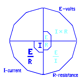
The Current Formula - (I) Section
In the second graphic the highlighted section
is the current formula: I = E / R.
Taking the voltage formula and dividing both
sides by R we get the current formula.
OK, What does this mean in words and in math?
Some current(I) will flow, based on
the voltage(E) push divided by resistance(R).
Find the circuit current for a 12 volt car light
with 4 ohms of resistance.
MATH:
Find some Current = 12(V) divided by 4(Ohms).
Giving ... current = (12 / 4) OR 3 Amps.
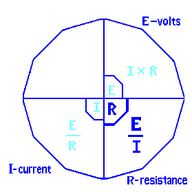
The Resistance Formula - (R) Section
This graphic highlights Resistance: R = E / I.
Some Resistance(R)
is some voltage(E) divided by some current(I).
MATH:
Find resistance with 9 volts at 1.5 amps.
R = (9 / 1.5) or 6 ohms of resistance.
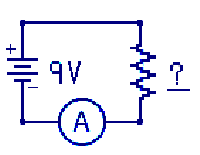
An example of these problems put into a circuit drawing might look like this. Using a 9V battery,
Amp Meter and an unknown resistor.
Find the resistor to give a 2 amp circuit? ___ohms
Find the current for a 9 ohm load resistor? ___amps
How low did to battery voltage drop if the circuit provided 4 amps at 2 ohms? ___V
In the next section we will start looking at larger circuits.
Answers: 4.5 ohms, 1 amp, 8 volts
The Power Formula
Adding the forth element to Ohms Law Pie Chart, POWER
, the formulas increased in complexity. With the
power option any of the 4 elements can be calculated if any two
elements are known.
Power is the amount of work being done. It is measured in Watts
named after James Watt. This work might be provided in heat, in
light, or measured in some other ways, like horsepower for example.
The basic Power formula is:
Power = volts x amps or P = E x I
How many watts are consumed in a circuit with 5 volts and 3 amps?
P = 5 V x 3 I which equals 15W.
If my cat, Gracie, bites through the wire feeding my 8 ohm,
100 watt speaker with the stereo on, will she get a shock from the voltage?
SO What is known? R and P. So find a formula on the chart with R ans P.
E = Sq Root of (P x R) where (8 x 100) = 800
E = Sq Root of (800) or 28 volts
Big ZIP.
28 volts to the mouth is a very high voltage!
Practical problems:
1) An automobiles starter motor will draw (uses) 300 amps to start
the engine. If the automobile has a 12 volt system how many
watts will it take to start the engine?
Answer: Did you get 3600 watts?
2) If you have a 1500 watt portable heater in your house and you
plug it into a 120 volt wall outlet how much current will the
heater need.
Answer: Did you get 12.5 amps?
3) Using the same portable heater in problem 2, you also want to dry
your hear with a 800 W hair dryer. Can you use both of them at
the same time, on the same bathroom outlet without tripping the
15 amp circuit breaker?
The answer is NO. Do you know why?
What is the circuit breaker was a 20 amp breaker?
Series Resistance
Method for calculating Series Resistance:
The total resistance of ALL resistors in Series will be equal to
the sum of the total of each of the individual resistors added together.
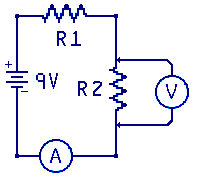
In this circuit diagram there are two resistors labeled R1 and R2 wired
in series. This means that all the current will flow through both R1
and R2. One question that comes to mind is how much current is that?
This circuit configuration is sometimes called a voltage divider. The
voltage across R1 and R2 adds up the the supply voltage of 9 volts. A second
question might be what is the voltage across R2?
Given: 9 volt supply, R1 is 270 Ohms, R2 is 750 ohms.
Find: Voltage across R2?
To solve this we need to have some total values
Step 1: Find the total resistance (R-equivalent) of the
series resistors in the circuit.
R-equivalent = R1 + R2 = 270 + 750 = 1020 ohms.
Step 2: Find the Total circuit current. I = E / R
I = 9volts/1020ohms OR 0.00882 ma which is round off to 9 ma
Step 3: Find the voltage across R2. E = I x R
E across R2 equals the I through R2, times resistance of R2
E = 0.009 x 750 or 6.75 V
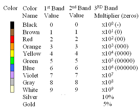
The Resistor Color Code
There are a host of color code systems and numbering systems used
within the field of electronics. Here is the basic resistor color
code system. Notice each color is associated with a number. For example
the color Orange with 3 and Blue with 6. The reason this is important
is that in early electronics, long before the concept of laser printing
was conceived, very small parts would have color dots or color bands on
them to represent their value. This practice continues today. Consider
a resistor with color bands red, violet, brown and silver. Its value is
270 ohm's. The first and second band colors represent actual numbers and
actual values. The third band color represents the number of zeros. If
the third band is the color brown then 1 zero is added e.g. brown ='0'
or if it is green then green = '00000'. Resistors are not exact values
so the forth band color is the tolerance. The tolerance is a plus or
minus percent, e.g. 270 ohms at 10 % could be any value between 243 and
297 ohms. This is 270 plus or minus up to 10 %
Going To The Work Bench
Experiment - The Voltage Divide
NOTES:
1) Do not build this project unless you have a volt meter to verity
your voltage readings.
2) Do not leave this circuit connected for an extended period of time
as it will discharge the battery.
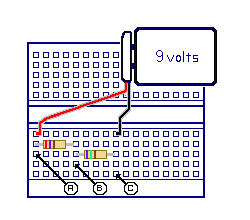
Build this experiment, following the instructions that accompany the kit.
Review the Resistor Color Code chart and wire up the kit as described.
Perform the lab, and record your results.
Parts List:
1 9-volt battery
1 Battery power clip
1 270 ohm resistor - R1
(red, violet, brown)
1 750 ohm resistor - R2
(violet, green, brown)
1 experimenters board
Miscellaneous:
hookup wire
The total resistance for series resistors can be calculated by
adding all resistances in the series together. There may be 3
or 4 or more in the series.
For this kit the total resistance: R-equivalent = R1 + R2,
is around 1020 ohms. The preciseness of the values will very
depending on the percent tolerance of the component in the circuit.
« Previous Chapter Next Chapter »
Email us: info@shoeboxkits.com