Chapter 4.3 - Voltage Divider

Go Home
Go To Introduction
This is Book 1
Chapter 1 - Electricity
Chapter 1.2 - The Numbers
Chapter 2 - Sharing and Bonding
Chapter 3 - Voltage
Chapter 3.2 - Voltage Static
Chapter 3.3 - Batteries
Chapter 3.4 - Solar - Others
Chapter 4 - Resistance
Chapter 4.2 - Parallel Resistance
Chapter 4.3 - Voltage Dividers
Chapter 5 - Semiconductor
Chapter 5.2 - PNP NPN Junctions
Chapter 6 - Capacitor
Back To The Guide
To Book 2
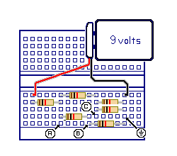
The Voltage Divider Lab
NOTES:
1) Do not build this project circuit unless you have a volt meter to verity your voltage readings.
2) Do not leave this circuit connected for an extended period of time as it will discharge the battery.
Build this experiment, following the instructions that accompany the kit.
Review the Resistor Color Code chart and wire up the kit as described.
Perform the lab, and record your results.
....Parts layout:
............R4
.......R1..........R5
............R2.....R6
.................R3
Parts List:
1 9-volt battery
1 Battery power clip
6 1k ohm resistors - R1, R2, R3, R4, R5, R6 (brown, black, red)
1 experimenters board
Miscellaneous:
hookup wire
Short Circuit and Open Circuit
A short circuit is when a section of a circuit fails due to a component having much
lower then expected or zero resistance. A short circuit can be simulated by placing
a wire jumper across a component. Many times circuits are not designed to allow
shorts so creating one is a poor idea.
In this book I have designed a few safe circuits where we will experiment with
planned short circuits We will use this concept to replace a switch as we move along
in the book.
Open circuits occur causing a circuit fails to work properly because a component
does not behave as if it is in a circuit. The component is called open.
In this section you will start building your trouble shooting skills.
You can either just run through the math or you can use the Work Bench trainer
and substitute R6 and measure the results as indicated in the problems. Either
way we will be using the combination circuit just discussed.
If R6 became a short circuit, or zero ohms on the diagram.
On the trainer, remove R6 and replace it with the jumper wire.
Find new voltage at Point A.
Find new voltage at Point B.
Find new voltage at Point C.
If R6 became an open circuit or just remove it from the diagram.
On the trainer, remove R6 or the jumper wire that replaced
R6 in the previous question.
Find new voltage at Point A.
Find new voltage at Point B.
Find new voltage at Point C.
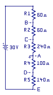
Simple Voltage Divider
A voltage divider can be a simple series circuit that divides up the supply
voltage (potential) into one or more lower levels of voltage (potential).
In an earlier example we had a 9 volt battery and two series resistors.
In this section, we have a longer voltage divider. In the schematic drawing, Point A
is the circuit common point. It is at some point mid way between the plus and minus
terminals of the battery. This divider provides both positive voltage and negative
voltage points within the same circuit. From Point A which in common, voltages at
Point B and Point C will be more positive than Point A. Point D and Point E will
be more negative to Point A.
Given: 30 volt supply
R1: 60 ohms
R2: 60 ohms
R3: 240 ohms
R4: 100 ohms
R5: 140 ohms
Calculate the voltage, with respect to Point A for:
Point B
Point C
Point D
Point E
Total series resistance is: (60+60+240+100+140) = 600 ohms
Total series current is I = E / R or ( 30 / 600 ) or 0.05 amps
Point B = voltage across R2 and R3: E = I X R
work: E = ( 0.05 X 300 ) = 15 volts at Point B
Point C = voltage across R3: E = I X R
work: E = ( 0.05 X 240 ) = 12 volts at Point C
Point D = voltage across R4: E = I X R (minus voltage)
work: E = ( 0.05 X 100 ) = -5 volts at Point D
Point E = voltage across R4 and R5: E = I X R (minus voltage)
work: E = ( 0.05 X 240 ) = -12 volts at Point E
« Previous Chapter Next Chapter »
Email us: info@shoeboxkits.com