Chapter 10 - IC's and OP-AMP's

This is Book 2
Chapter 7 - AC and Hertz
Chapter 8 - Magnetism
Chapter 8.2 - Inductors
Chapter 9 - Power Supply
Chapter 9.2 - Power Supply Filters
Chapter 10 - IC's and Amplifier
Chapter 10.2 - OP AMP Feedback and Unity Gain
Chapter 10.3 - OP AMP Non-Inverting
Chapter 10.4 - OP AMP Inverting
Chapter 11 - 555 Timer
Chapter 11.2 - Counters
Chapter 12 - Logic
Back To The Guide
Take Me Home
Operational Amplifiers
With some of the fundamentals established, it is time to start connecting
components into systems.
This chapter is about Operational Amplifiers (Op Amps). Specifically,
Op Amps in integrated circuit (IC) packaging. Along with the introduction
of OP Amp IC's this chapter will also introduce the concept of the Black Box.
The Black Box
Taking an example from the automotive industry, consider the possibility that
some drivers and passengers have little or no knowledge of the internal
workings of an automobile engine. The engine represents a BLACK BOX to the
automobile user. You need to know little or no technical information about
how the engine works internally to use the engine to propel the car.
You are separated from the engine by an abstraction layer. In your layer
you have a key, a gas cap, a gas peddle, lights, sounds and service people.
If your financial means and/or resources are substantial, you may just have
people and summon the car and its driver at will, and that is the extent of your
need-to-know.
Likewise, in electronics, there are untold numbers of black box IC's. We will
discover a few different IC's, some basics about how they work and how to use
them. That is our level of a need-to-know, at this time in the study.
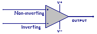
Schematic Symbol
These are schematic symbols for the Op Amp. The first symbol is without the power supply
leads drawn in. Sometimes the power supply leads are not shown anywhere on the drawings.
However you will need them for the IC to work.
The second graphic shows the power supply pins-outs (leads).
There is no one general or universal Op Amp package or pin configuration.
If the device has a single amplifier, the package MAY,
have 8 pins or leads, but not always. Configurations are
available with 2 and even 4 amplifiers within a single case (package).
Additionally, some amplifiers can provide higher output power, higher frequencies, wider
operating temperatures, faster switching speeds, or special functions.
This is why there is no general Op Amp type or case size.
Looking at the second graphic, these are the 5 common connections to consider for any
general Op Amp. There are two power connections, for the V+ and V- power supply.
There are two input connections for non-inverting (+) and inverting (-) inputs.
These is one output connection.
Here is a list of general Op Amp Rules:
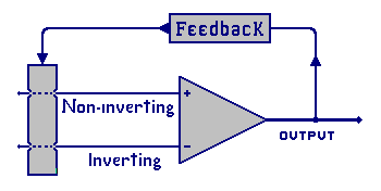
1) The Op Amp, working as an amplifier, will have some type of
feedback circuitry. Without this feedback circuitry the
Op Amp works as a comparator or a switch circuit. The
feedback will try to keep the two input voltages at the
same potential. The feedback might be very complex or as
simple as a resister, capacitor, inductor, or a wire to
connect the output potential back to an input.
a) The output voltage equals the input voltage plus the amplification factor.
b) The output voltage is fed back to the input.
c) Op Amp inputs are the sums of all input source voltages plus all feedback voltages.
d) Negative feedback is the feedback applied to the inverting input.
e) Positive feedback is applied to the non-inverting input
f) Without feedback the Op Amp works as a switch
2) The Op Amp is a voltage amplifier with the capability to provide a very high voltage gain.
3) The Op Amp has a range of acceptable operating power supply voltages that it must stay within.
4) The input voltage must not exceed the power supply voltage.
a) It can not be higher(more) than the V+ supply voltage
b) It can not be lower (less) than the V- supply voltage
5) The inputs do not draw current. (in theory )
6) As a comparator the Op Amp will compare the inverting and non-inverting
inputs. When the non-inverting is more positive than the inverting the
output voltage will be near V+. If the inverting is more positive the
output will near the V-.
Remember that these are only general Rules!
Op Amp Power Supplies
Single Rail Supply: A power supply with two terminals (leads) is called a single rail
power supply. A 9V battery is a single rail supply with
two terminals labeled (-) and (+), and (about) 9 volts difference between them.
If the common circuit point is the (-) minus terminal of the supply, the
other terminal is the +9V rail (with respect to the common). If the
common terminal is the (+) positive terminal then the other terminal is
the -9V rail.
Recall from the voltage divider examples in an earlier chapter that, sometimes
the circuit common,
(ground), is not directly associated with the V+ or V- supply voltage.
In Op Amps the common or ground voltage may be associated with the inputs and
the output potential. This should become clearer in a few paragraphs when we
look at the single rail supply using a voltage divider
in a non-inverting input amplifier configuration.
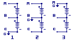
Dual Rail Supply:
Power supplies with three terminals (leads) are called two-rail or dual rail
supplies. In this graphic there are two battery sets made up with 2- 9V batteries.
The supply plus rail, V+(point A), minus rail, V- (point C), and the supply center
(point B) can different then the circuit common, sometimes called circuit ground (point G).
Supply 1 has point G (circuit ground) at the rail V- portion of the supply.
For supply 2, G is the center voltage
and for supply 3, G is at rail v+.
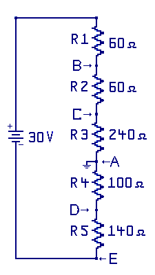
Here is a graphic from an earlier section on voltage dividers. This same
technique will be used for providing simple voltage sources, and used for a
simple feedback network.
We will discuss voltage dividers used in feedback circuits in the
upcoming section. They are a common practice in building amplifiers,
as well as providing reference voltages in op amp circuits.
« Previous Chapter Next Chapter »
Email us: info@shoeboxkits.com