Chapter 9.2 - The Power Supply.

This is Book 2
Chapter 7 - AC and Hertz
Chapter 8 - Magnetism
Chapter 8.2 - Inductors
Chapter 9 - Power Supply
Chapter 9.2 - Power Supply Filters
Chapter 10 - IC's and Amplifier
Chapter 10.2 - OP AMP Feedback and Unity Gain
Chapter 10.3 - OP AMP Non-Inverting
Chapter 10.4 - OP AMP Inverting
Chapter 11 - 555 Timer
Chapter 11.2 - Counters
Chapter 12 - Logic
Back To The Guide
Take Me Home
Filtering the power
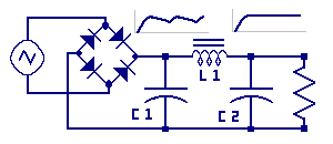
Look at this circuit. We are bringing many components together to build this power
supply. Starting on the left side we see the symbol for an alternating current
source. Remember that this is a general symbol representing an AC voltage from any
source. These, might include power from a wall outlet, wind generator, from the secondary coil of
a transformer, or from test equipment called a signal generator.
BRIDGE RECTIFIER:
The AC source is applied to the bridge rectifier which converts the voltage to DC.
Recall this diode arrangement converts both half's of the AC wave form into a DC output.
CAPACITOR C1:
Next recall from the section on the capacitor that this C1 can store energy on its plates
when the surrounding voltage is higher then the plate voltage. C1 release voltage
back into the circuit when the plate voltage is higher then the circuit voltage. Another
characteristic is that the bridge rectifier is such a powerful source to C1, that C1 changes nearly
instantaneously from the supply. Next, providing the load on the power supply is sized correctly
the capacitor will be able to provide voltage back into the circuit without being
drained much before the next boost of power comes from the rectifier.
In this illustration C1, called a filter capacitor, is filtering or removing some of the ripple from
the rectifier voltage through its ability to store and return energy.
INDUCTOR L1:
From the inductor section we learned that inductors also store energy, however in an
electromagnetic field. The voltage at the left side of L1 has a small amount of ripple
due to C1 not being able to store and release enough energy so some amount of ripple
remains and needs to be
filtered out. As current flowing through L1 it builds up
flux lines in L1's magnetic field. When C1 voltage dips in voltage level
this change causes a voltage change across L1. Inductors oppose voltage changes. The
voltage change causes a slight breakdown in flux lines and L1 generates electromagnetic
energy keeping the output voltage on its right side relatively constant.
CAPACITOR C2:
A second filter capacitor is placed at the output of L1 to help eliminate
any final ripple in the power supply output voltage.
Lastly is a load resistor. The reason we want a supply is to
provide power to some load we want to power.
This is an OKAY power supply.
Where to go from here?
For a more in depth look at power supply, you will be able to look into the power
supply labs. There we will provide a dive into some different types
of supplies, how they work and how to use them.
For now, when we see a circuit with a battery, or a power supply voltage we should
consider the source voltage as coming from any type of source. When we get a
voltage from some source, we can use it "as is" reduce it with a voltage divider
or change the level using a more sophisticated power supply.
In the next chapter we will start looking at higher level circuits and how each
might use different power supply arrangements.
« Previous Chapter Next Chapter »
Email us: info@shoeboxkits.com