Chapter 9 - The Power Supply

This is Book 2
Chapter 7 - AC and Hertz
Chapter 8 - Magnetism
Chapter 8.2 - Inductors
Chapter 9 - Power Supply
Chapter 9.2 - Power Supply Filters
Chapter 10 - IC's and Amplifier
Chapter 10.2 - OP AMP Feedback and Unity Gain
Chapter 10.3 - OP AMP Non-Inverting
Chapter 10.4 - OP AMP Inverting
Chapter 11 - 555 Timer
Chapter 11.2 - Counters
Chapter 12 - Logic
Back To The Guide
Take Me Home
We Got Power Now... Baby
This section will introduce Power Supplies. In the circuits in prior
sections we relied on a battery as the source of power. Batteries are good for
portable circuits but not very good for long lasting power. If we can harness a
power source that is sustainable then we can consume even more power. We
might even be able to recharge our batteries using a sustainable power
source. So where do we begin?
Halfwave Rectifier Power Supply
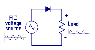
We will start this chapter by introducing the HalfWave Rectifier power supply.
First we will introduce the parts then we will break apart the meaning of it name.
Looking at the left
side of the illustration, we see the symbol with a sine wave inside a circle. This
represents any alternating current generator. Along the top is a diode, also
knows as a rectifier. On the right side is a resistor representing the load.
Note the sine wave graph directly below the words
AC voltage source. You should recall from an eariler section that a diode
is a one-way gate only allowing electrons to flow in one direction. You should also
recall the graphs from the AC section. They showed that the
voltage starts at the zero line and increases over time to its positive peak
voltage, then moves back to the zero line over more time. This is half the
sine wave. Next the voltage moves in the negative direction to that peak
voltage and then again back to the zero line after some more time. This is
the second half of the sine wave.
Now look at the name Halfwave rectifier power supply. During the first
half of the sine wave cycle, current is flowing through the rectifier (diode).
Electrons are flowing out the lower generator terminal, which is negative
voltage, through the load resistor, through the forward biased diode and
back into the positive terminal of the generator.
During the second half of the sine wave cycle the diode is reversed biased
thus no electrons (current) is flowing.
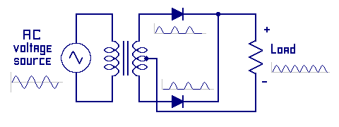
Fullwave Rectifier Power Supply
This is a fullwave rectifier power supply. This supply takes advantage of both
half's of the sine wave, thus gaining more available power and provides a smoother
output voltage.
The left side of this illustration has the same AC voltage source as in the prior example.
The next item is an iron core transformer. This transformer has a center tapped secondary
coil. Want that means is that the coils are wound on an iron core. The secondary coil
had two end terminals and a center-tapped terminal. There are two diodes and a load resistor.
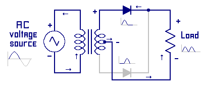
Look at the fullwave rectifier circuit for the first half of the sine wave cycle.
Recall that the changing fields from the AC voltage source connected to the primary coil
of the transformer will induce energy into the iron core, which will induce
voltage to the secondary coil. During this first halfcycle the top terminal of the
transformer secondary is the most positive and the bottom terminal of the transformer
is the most negative. The current can not flow out the bottom terminal due to the lower
diodes reverse biased state.
Electrons will flow out the center tapped terminal of the transformer, which is negative
voltage compared to the top terminal. Electron flows through the load resistor, through
the top diode, which is forward biased and back into the positive (top) terminal of the
transformer.
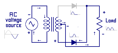
Look at the circuit for the second half of the sine wave cycle. During this cycle the
bottom terminal of the transformer secondary is the most positive and the top terminal
of the transformer is the most negative. The current can not flow out the top terminal
due to the upper diodes reverse biased state.
Electrons will flow out the center tapped terminal of the transformer, which is negative
voltage compared to the bottom terminal. Electron flows through the load resistor,
through the lower diode which is forward biased and back into the positive (bottom)
terminal of the transformer.
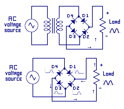
Fullwave Bridge Rectifier Power Supply
This is a fullwave bridge rectifier power supply. This supply can be used with
or without a transformer. This 4-component arrangement of the diodes is called a bridge.
During the first half of the sine wave cycle the lower portion of the bridge is negative
portion coming from the AC source. The current flows through D3, then through the load
resistor, then through D1 and back into the positive portion of the AC source. Diodes D2
and D4 are reverse biased so no current flows.
During the second half of the sine wave cycle the upper portion of the bridge is negative,
coming from the AC Source. The current flows through D4, then through the load resistor,
then through D2 and back into the positive source. Diodes D1 and D3 are reverse biased so no
current flows.
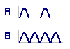
Ripple
Next we will look at the output ripple. Ripple is the fluxuation in the output voltage.
In most cases this is undesirable. An example of ripple in an audio circuit is a low
pitched buzzing or humming sound. Ripple can be reduces buy filtering it. In this
illustration, the halfwave rectifier output is A and the fullwave rectifier output is B.
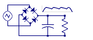
Recall from the capacitor section that a capacitor resists a change in voltage. If the
supply voltage is less then the stored voltage in the capacitor (cap), the cap will
want to give back electrons. If the supply voltage is higher, the cap will tent to take on electrons.
By adding a filter capacitor, the power supply can stores energy in the capacitor. During
the portion of the cycle when the input voltage is less then the capacitor voltage, the
capacitor will give energy back to the circuit. This will level- out the ripples. The more
filtering, the less ripples. If the supply LOAD is very small, the capacitor can remove all noticeable ripples.
« Previous Chapter Next Chapter »
Email us: info@shoeboxkits.com