Chapter 8 - Transforming Energy

This is Book 2
Chapter 7 - AC and Hertz
Chapter 8 - Magnetism
Chapter 8.2 - Inductors
Chapter 9 - Power Supply
Chapter 9.2 - Power Supply Filters
Chapter 10 - IC's and Amplifier
Chapter 10.2 - OP AMP Feedback and Unity Gain
Chapter 10.3 - OP AMP Non-Inverting
Chapter 10.4 - OP AMP Inverting
Chapter 11 - 555 Timer
Chapter 11.2 - Counters
Chapter 12 - Logic
Back To The Guide
Take Me Home
Fundamentals of Magnetism, Inductors and Transformers
You may recall from the Electromagnetic Generation section, when a wire
passes by (cuts) a magnetic field, electricity is generated. The
current flows in a specific direction through the conductor. This
direction is described by the Left-hand Rule. The reverse is also true.
When a wire has current flowing through it, a magnetic field is created.
More specifically, this is called an electromagnetic field. We use
electromagnetic fields everyday and don't give them much thought. When
we turn on our cell phones, start our automobiles, and turn on a light
switch we cause current to flow and electromagnet fields are generated.
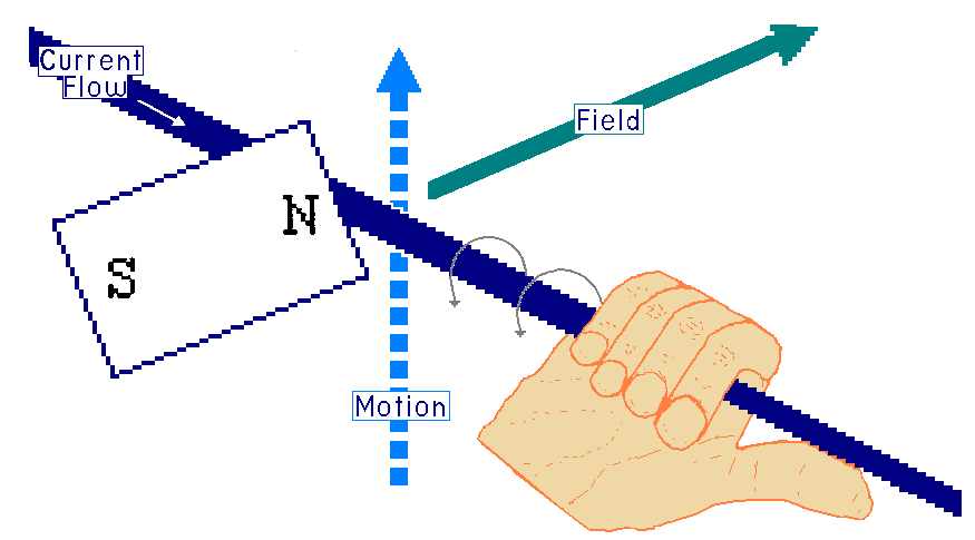
Electromagnetism is described by the Right-Hand Rule. In this image I
have combine the Left-Hand Rule with the Right-Hand rule.
Left-hand Part:
The motion of the conductor moves vertically along the face of the North
Pole of the magnet. The magnetic flux (field) radiated out from the North
Pole. The wire, cutting the field, causes current to flow down the conductor.
Right-Hand Part:
On the right side of the depiction, the thumb pointing in the same direction
of the current flow. There are magnetic field rings circling the conductor,
moving in the direction of the fingers as they wrap around the conductor.
This property of inducing these field rings is called electrical induction.
The general idea is that when a conductor is in a changing magnetic flux
field, it is an inductor. This is the case when the conductor is consuming
energy and supplying the electromagnetic field or is absorbing the
electromagnetic field energy and generating an Electro Magnetic Force (EMF
also called voltage). The unit of measurement for induction, and for an
inductor is the Henry. The unit, Henry, is named in honor of the American
scientists Joseph Henry. The alpha character representing the Henry is L.
Inductors are often labeled with the letter L.
With a single contactor, the current produced by crossing the magnetic flux
(field), will not be strong enough to produce much electricity or benefit at
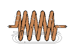
this point in our study. However, when we wrap the wire into a coil and the
coil passes the magnet, each loop on the coil creates small magnetic flux
lines. Because of the construction of the coil these flux lines will be added
together create a stronger induced voltage. With five loops of wire the voltage
is 5 times that of a single loop of wire.
This is a bi-directional effect. So when we apply a voltage to the coil of wire,
with say 200 loops in the coil, there is a concentration in flux lines that
built up in a small area. If we take this same coil and wrap it on an iron
core, like a nail or steel rod, this magnetic field is transferred into the
iron core and is present as long as the current is flowing through the coil.
This is a simple electromagnet and it operates on the electromagnetic field
within the iron core.
Here is a short recap: To this point we have a coil of wire. If this coil
passes by a magnetic field, a voltage is generated across the coil. As well,
if a voltage is applied to the coil an electromagnetic field is created. This
is the basic idea behind how door bells work, speakers make sound and motors
turn. But there is more here.
Induction and Back EMF
When the current flowing through coil suddenly stops flowing, there is no
energy to keep the electromagnetic field stored in the iron core. So this
stored field starts breaking down. This also produces a change in the magnetic
field. This breaking down is in the reverse direction of the building up of the
field. Looking at the Left-hand Rule the change in the magnetic field is in the
reverse direction. In effect, the action caused by the collapsing flux lines
passing through the coil of wire generates a voltage within the coil, due to the
inductive properties. However, this time the current is flowing in the reverse
direction. This is called Reverse EMF or Back EMF. Shortly you will learn when
and how to use Back EMF and when to protect a circuit from the effects of Back EMF.
The scientist, Faraday noted in his work that the level of EMF is proportionate
to the speed of the field changing. Inductance does not resist the flow of
current, it resists the CHANGE in the flow of current.
Transformer
If a second coil (or more) of wire is wrapped on the same core as the first coil
and is close enough that the magnetic field from the first coil crosses this
second and other coils, this configuration is a special inductor called a
transformer. For a transformer to function, it needs a change in the flux fields
to causing induction.
NOTE: The core does not need to be made of iron. For a transformer to exist, two
or more coils just need to share the same flux lines. This means they could be
wrapped together with a core made of paper or plastic or together with no core at all.
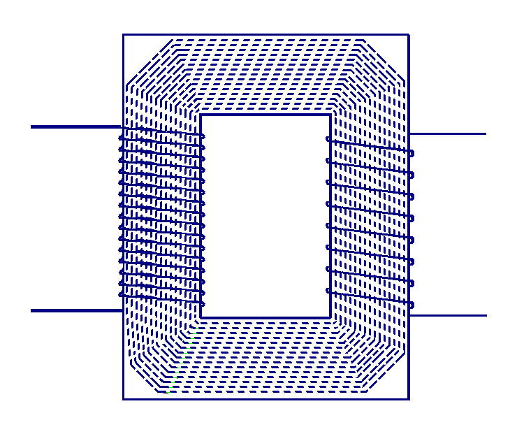
Turns Ratio, Voltage Ratio, Current Ratio
In the transformer illustration above, the coil on the left side has 15 turns
and the coil on the right coil has 7 turns. The turns ration for a transformer
is the same as the voltage ratio. In this transformer the turns ration is
15-to-7, so if 15 volts of alternating current is applied to the left side,
7 volts comes out the right side. The current ration is inversely proportional
to the voltage ration. If 15 volts at 2 amps is being supplied on the left coil
of the transformer (about 30 watts of input power). Ignoring any efficiency losses
within the transformer, the output will also be 30 watts. Ohms Law states that
30 watts divided by 7 V yields about 4.25 amps of output current.
These ratios work the other direction also. Looking at a transformer with the
input coil, also called the primary coil, with 100 turns, and two outputs or
secondary coils, one with 50 turns and the other with 250 turns. If the input
voltage is 10 volts, then the outputs are 5 volts and 25 volts, respectively.
« Previous Chapter Next Chapter »
Email us: info@shoeboxkits.com